Chamfer tool
|
Tool |
Tool set |
Shortcut |
|
Chamfer
|
Basic |
Alt+7 (Windows) Option+7 (Mac) |

The Chamfer tool places a chamfer, or line, between two objects or adjacent sides of an object, including rectangles, NURBS curves, polygons, 3D polygons, polylines, or line segments. A chamfer cannot be placed between parallel lines or NURBS curves.

|
Mode |
Description |
|
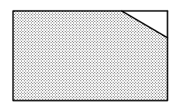
Standard
|
Places a chamfer without affecting the original object; to create a single object, group the chamfer and the chamfered object together
|
|
Split
|
Places a chamfer and splits the chamfered objects. This mode extends lines, if needed, for the chamfer to connect. To create a single object, group the chamfer and the chamfered object together. If the corner of a polygon is chamfered, the chamfer takes the place of the corner.
|
|
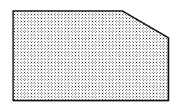
Trim
|
Places a chamfer and trims the chamfered objects. If the corner of a polygon is chamfered, the chamfer takes the place of the corner. This mode extends lines, if needed, for the chamfer to connect.
|


To create a chamfer:
Click the tool, and then click the desired mode.
To specify the chamfer size with a different method (for example, by a set chamfer length), click Preferences. The Chamfer Settings dialog box opens. Enter the appropriate values.
Click to show/hide the parameters.Click to show/hide the parameters.
|
Parameter |
Description |
|
Entry Options |
Select a method for specifying the chamfer size; once selected, the required entry fields also display on the Tool bar for easy entry |
|
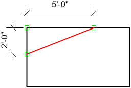
First and Second Lines |
Enter the distances from the end of the First Line and Second Line at which to place the ends of the chamfer line
|
|
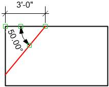
First Line and Angle |
Enter the distance from the end of the First Line at which to place one end of the chamfer line, and enter the Angle between the First Line and the chamfer line
|
|
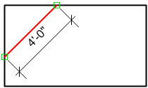
Chamfer Line Length |
Enter the Chamfer Line Length
|
Fields on the Tool bar indicate where the chamfer will be placed, according to the current settings in the chamfer preferences. Change the default values if necessary.
The available fields vary based on the entry option selected in the Chamfer Settings dialog box.
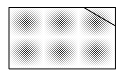
Click the object where the chamfer will begin.
Click the object where the chamfer will end.
The chamfer is drawn according to the mode selection.
